Project: Firefly jar

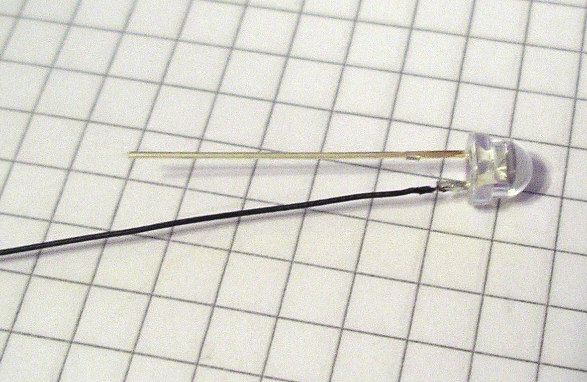
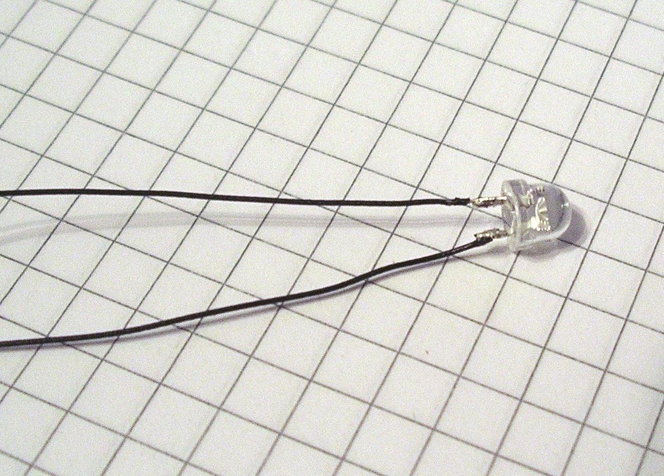
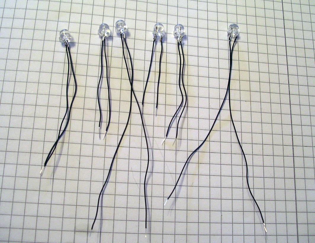
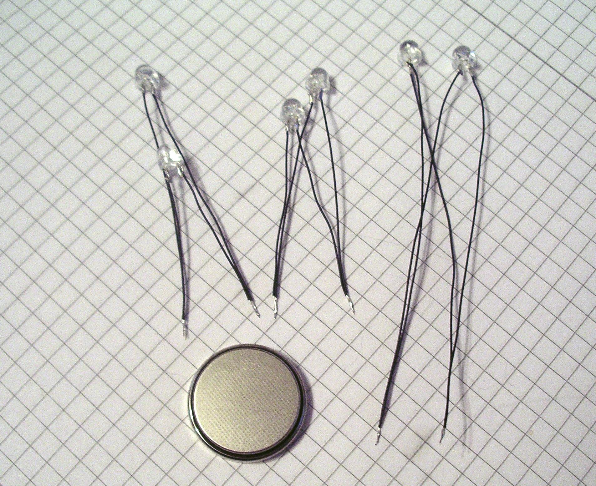
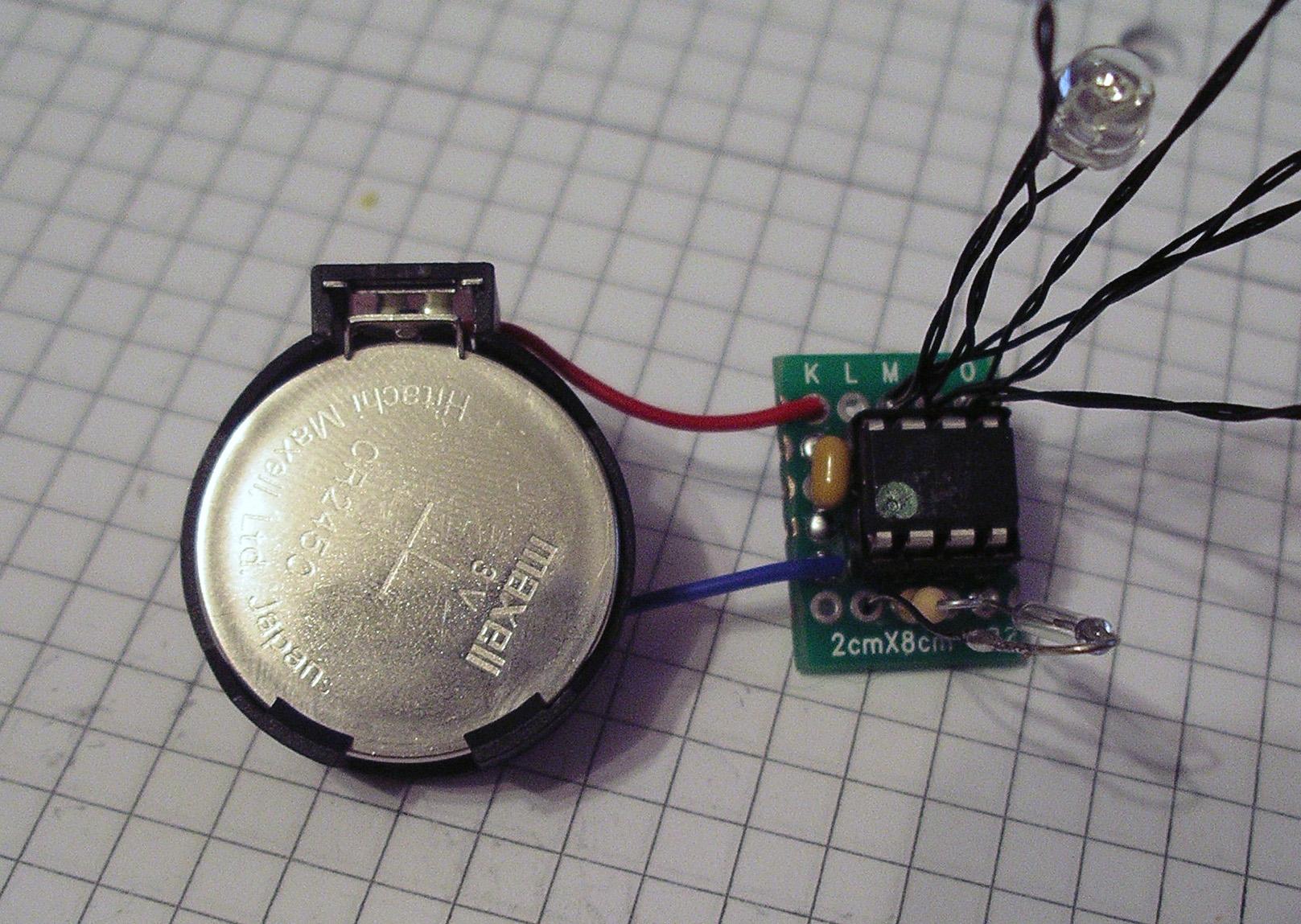
This magic jar contains little LED "fireflies" which light up in random patterns. It's a perfect gift or ornament for a desk, a night table, etc. The jar uses very little power and will run for years on a single battery.

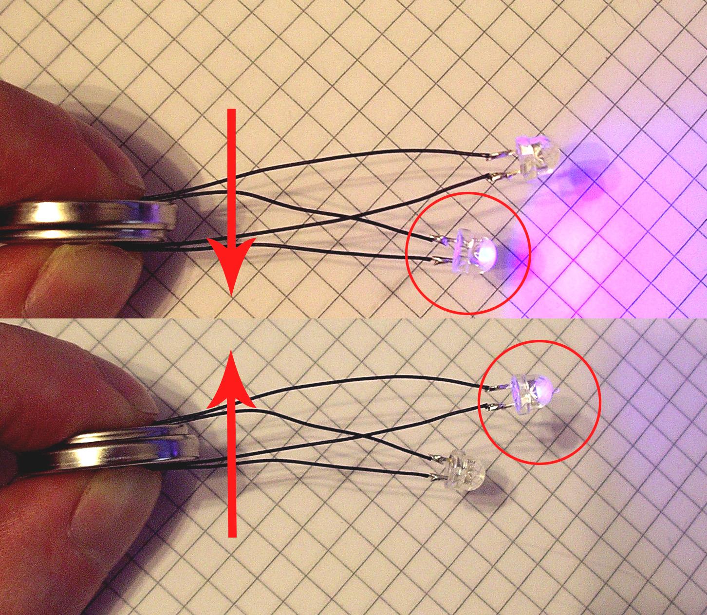
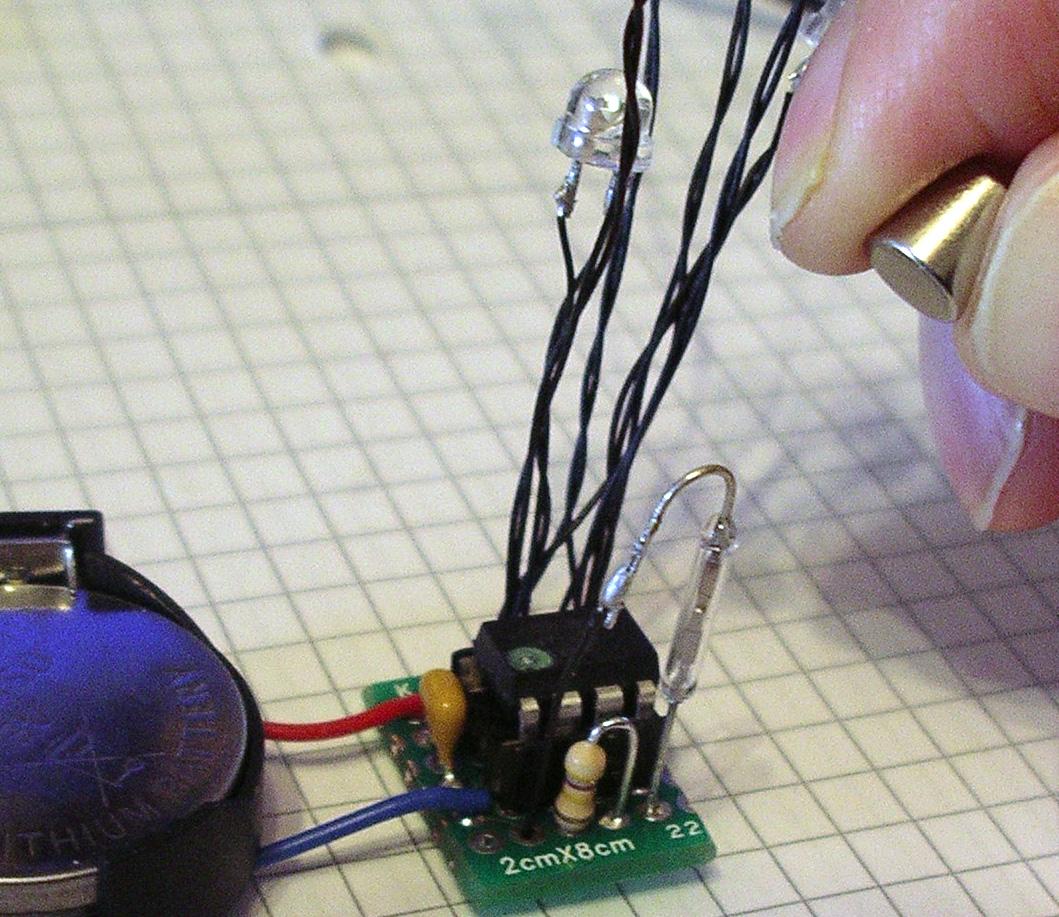
There's no visible switches or mechanisms on the jar, it operates with a little magnetic "key" and by sensing when somebody touches the lid.

Every jar is as individual as the maker, you can decorate it however you want. Here we only cover the electronics that make it work.

The Tiny85

The "brain" of our jar is an Atmel Tiny85. The Tiny85 es from the same family as the Mega328 chip found in an Arduino Uno but it only has 5 I/O pins instead of 20.

Here we see the chip's pins:

Pin 1 ("Reset") is marked by a little dot on the chip. It's vitally important to orient the chip correctly when we use it. The chip could be damaged (or even drestroyed!) if we connect it backwards.

In our jar, three of the pins control the LEDs and two of them are used for sensors (one for the magnetic switch and one for the touch sensor).

Components
We will need the following components to build the jar:
  • An Atmel Tiny85V + 8-pin socket.
  • A piece of prototype board with 5x6 holes.
  • 6 LEDs
  • 3 Volt coin cell + holder (we recommend a CR2450)
  • One 500,000 Ohm resistor
  • A 1uF ceramic capacitor (must be ceramic type!)
  • A small ("Reed switch")
  • A small magnet
  • Some fine wire to connect the LEDs (the finer, the better...)

Note: We use the low voltage ('V') version of the Tiny85 because we're working with a 3V battery. Do not use the normal version of the chip.

We also need a jam jar with a metal lid and some stuff to decorate it. Try to find an interesting shape jar (eg. hexagonal). Fancy jars distort light and people have to look a bit closer to see what's inside. :-)

Construction - PCB

Place the socket on the PCB as shown in the photo and solder the 8 pins in place underneath the board.

Important: The pins of the socket are aligned horizontally.

Insert the ceramic capacitor in the board in the position shown.

Underneath the board, bend, cut and solder the legs of the capacitor as shown.

Important: Make sure you leave a gap between the long leg of the capacitor and the three pins of the chip socket.

Next, add the 500k Ohm resistor.

Insert it in the PCB as shown, with the body on the left.

The orientation of this resistor is important for the touch sensor to work, you MUST insert it exactly as shown in the photograph!

Underneath the PCB, bend, trim and solder the legs of the resistor as shown.

Construction - LEDs

Cut off the legs of the LEDs close to the LED body and replace them with a piece of wire as shown.

nb. It's easier if you do the legs one at a time.

Use a color of wire that matches whatever you're going to put inside your jar (so it's harder to see it). The finer the wire, the better.

Make another 5 LEDs like the first one. Use a different length wire for each LED so they'll be at different heights inside the finished jar.

Conect the LEDs in three pairs.

The two LEDs in each pair should be connected in opposite directions. LEDs have a flat spot on their body to identify their orientaion.

Check each pair of LEDs with the battery to make sure you got the orientation correct when you made the pair.

Connect the battery both ways, only one of the two LEDs should light up when you connect it. You should be able to light up the other LED of the pair by reversing the battery.

When you're sure the LED pairs are correct, take two of them and join them together.

Insert the four wires into the second hole of the PCB as shown in the photo.

Bend the wires underneath the PCB and solder them to the pin of the socket.

Take the third pair of LEDs and join it with the loose wire of one of the pairs connected to the PCB.

Insert the four wires in the first hole of the PCB as shown in the photo.

Bend/solder the wires undernath the PCB as before...

Join the remaining loose ends together and insert the four wires into the third hole of the PCB.

Bend/solder underneath...

To finish up, twist each LED between your fingers to join its wires together. This makes the LEDs much easier to position inside the finished jar.

Construction - Reed switch

Place the reed switch in the PCB as shown. Don't push it all the way in, leave some exposed leg (about the same height as the resistor is good).

Bend/trim/solder it underneat the PCB (nb. it connects to the same pin as the long leg of the capacitor).

Bend the other wire of the switch to make a loop as shown.

Note: The glass of reed switches is extremely delicate! Do not bend the wire near the glass. Hold the wire near the glass with your fingers as you bend it.

If you put any pressure at all on the glass it will shatter...you have been warned!

Add a short piece of wire to connect the reed switch down to the PCB.

Connect the wire from the switch to the resistor under the board.

(nb. Connect to the resistor, do not connect it to the pin of the chip socket!)

Construction - Battery

Connect two wires to the battery holder as shown in the photograph.

(It's best to use different colored wires, eg. red/blue for positive/negative).

Connect the wires to the PCB, one on each side of the capacitor.

Important: The positive wire (the red on in the photo) goes to the same side of the PCB as the LEDs.

Bend the wire underneath the PCB and connect it to the wires of the capacitor.

Construction - Install the Tiny85

Next we have to install the Tiny85 chip in the socket.

With new chips you normally have to press the legs against a flat surface to make them fit easily.

Insert the chip into the socket. Pin 1 of the chip goes on the size near the resistor.

If you got a preprogrammed chip from me it will have a dot of paint to indicate pin 1.

If not, look for the little pin 1 indicator on the chip. It can be difficult to see but make sure you get it correct.

Construction - Let's light it up!

Insert the battery in the holder.

If everything is correct you should see the LEDs start to flash in short sequences.

If not, remove the battery and carefully check all your wires and solder joints.

If we place the magnet near the reed switch the "flies" should turn on/off. You'll see two quick flashes for "on" and four quick flashes for "off".

Construction - Touch sensor

Solder a wire to the top part of the resistor.

(nb. This is why the orientation of the resistor was important - this wire needs to connect to the correct part of the circuit...)

Insert another, longer wire to the the hole in the corner of the PCB near the battery.

Bend the wire underneath and solder it to battery/capacitor wires.

Sandpaper a small spot on the lid of the jar near the edge and apply a blob of solder.

Make sure the solder flows/sticks to the lid properly.

Place the circuit on the lid. Place it so that the loop of wire of the reed switch is on the outside. The switch needs to be near the side of the jar when we put the lid on, you can bend it outwards if necessary (be careful not to break the glass).

When you're happy, solder the short wire to the lid.

Double check the position (make sure the lid will still go on the jar!) then glue the circuit in place. Make sure the PCB and battery are slightly separated from the lid so there's no electrical contact between circuit/lid.

To complete the touch senser we need to attach a piece of metal foil to the end of the long wire.

With the foil connected you should see the LEDs flash rapidly every time you touch the lid of the jar.

If it doesn't work, try turning it off/on with the magnet. If it still doesn't work, you probably need more foil. Use a bigger piece of foil or add another layer.

(nb. Make sure the foil isn't touching the lid like it is in the photo!)

Construction - how to hide the foil

The foil needs to be hidden in the jar, here are two ways to do this.

One way is to use a piece of colored paper as a background to your jar. If you do this the foil can be sandwiched between two pieces of paper.

Again: Make sure it works before you glue it all together. If not, add more foil...

Another way to do it is to hide it at the bottom of the jar.

This works well if your jar has a decorated base like the "ground" layer in our ladybird jar.

(Make absolutely sure you have enough foil to work reliably before you put it all together...!)